BLOG
BLOG
What Tolerances Matter Most in Gearbox Manufacturing
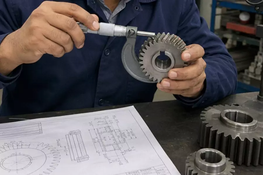
When it comes to power transmission, the margin for error is measured in microns. Whether dealing with a high-speed automotive transmission, wind turbine mechanics, or heavy-duty industrial drives, the ultimate reliability of the system comes down to one critical factor: precision engineering.
But with dozens of moving parts, exact specifications, and environmental variables at play, determining exactly what tolerances matter most in gearbox manufacturing can be a complex challenge. In this article, we will dive deep into the specific measurements and clearances that dictate a gearbox’s performance, efficiency, and operational lifespan.
The Core of the System: Gear Geometry and Profile
At the heart of gear manufacturing is the gear itself. While the overall diameter and thickness are important, the microscopic geometry of the teeth dictates how smoothly power is transferred.
Gear tooth profile accuracy is arguably the most critical metric here. A gear tooth operates on a precise involute curve. Any deviation from this ideal shape means the teeth will not roll smoothly against one another. Instead, they will scrape, bump, or bind. To prevent this, engineers spend significant time calculating gear mesh contact patterns. By understanding exactly where and how the teeth will meet under load, manufacturers can apply micro-modifications—like tip relief or crowning—to ensure the load is distributed evenly across the tooth flank.
Furthermore, the surface texture cannot be ignored. The surface finish impact on gear tooth friction is profound. A rough surface will break through the protective lubricating oil film, leading to metal-on-metal contact, increased operating temperatures, and accelerated wear. Super-finishing processes are often required to achieve the mirror-like flanks necessary for high-efficiency drives.
The Foundation of Reliability: Housing and Alignment
Even the most perfectly machined gear is essentially useless if it is not held in the correct spatial position. The gearbox housing acts as the rigid skeleton of the entire assembly.
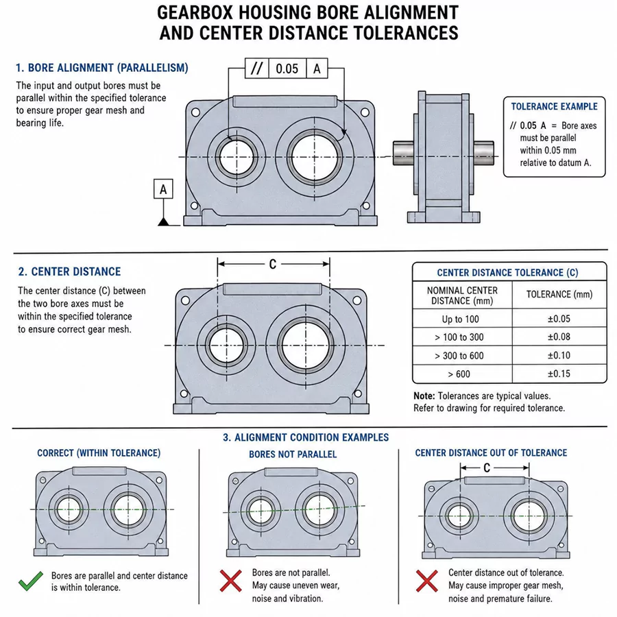
Perfect gearbox housing bore alignment is strictly required to keep gear shafts exactly parallel (or accurately intersected, in the case of bevel gears). If the housing bores are misaligned by even a fraction of a millimeter, the gears will suffer from edge loading, where all the transmitted force is concentrated on one small corner of the gear tooth.
Additionally, the distance between these bores is heavily scrutinized. The consequences of excessive center distance deviation can be catastrophic.
- Too close: The gears will bind, destroying the lubrication film and causing immense friction.
- Too far apart: The gears will have weak engagement, leading to a high risk of tooth breakage and excessive play.
To ensure shafts spin perfectly true within these bores, measuring shaft runout and concentricity is a standard quality control practice. Runout creates an eccentric “wobble” that sends damaging vibrations rippling through the entire mechanical system.
Managing Clearances, Backlash, and Axial Play
Mechanical systems need room to move and accommodate lubrication, but uncontrolled movement is the enemy of precision.
In robotics, aerospace, and CNC machinery, the backlash requirements for high-precision applications are incredibly stringent. Backlash is the slight clearance or “play” between mating gear teeth. While zero-backlash is often the holy grail for positioning accuracy, a microscopic amount of clearance is physically necessary to allow oil to coat the teeth.
Managing this internal space extends to the shafts as well. Optimizing gear assembly axial play prevents rotating shafts from sliding back and forth along their axis. Excessive axial play can force gear teeth out of alignment and put unintended stress on retaining rings and internal seals.
Engineers must also look beyond room-temperature measurements. The impact of thermal expansion on gear clearances is a major design consideration. A gearbox operating under heavy load at 90°C will have completely different internal dimensions than it does at rest. If the housing is made of aluminum (which expands quickly) and the gears are steel, the tolerances must be engineered to accommodate these differing thermal expansion rates without causing the system to lock up.
Bearing Integration and Material Dynamics
The rotating assemblies in a gearbox rely entirely on bearings to minimize friction. However, a bearing is only as good as the pocket it sits in.
Strict bearing seat tolerances for gearbox longevity are non-negotiable.
If a bearing seat is machined too loosely, the bearing’s outer ring will spin inside the housing, eventually gouging out the metal and destroying the enclosure.
If machined too tightly, the press-fit will crush the internal rolling elements of the bearing, leading to immediate overheating and premature failure.
Balancing these dimensional needs often brings us to a complex metallurgical challenge: material hardness vs dimensional stability. To make gears durable, they must be heat-treated and hardened. Unfortunately, the intense heat required for this process almost always causes the metal to warp. Modern gearbox manufacturing tolerances require advanced post-heat-treatment grinding to correct this warpage and bring the component back to its exact dimensional requirements.
Standards, Quality Control, and Noise Reduction
That familiar gearbox “whine” is rarely mysterious. In most cases, it tracks back to transmission error (TE)—the small, repeatable speed variation that occurs as the teeth engage and disengage. TE shows up as tonal noise at the gear-mesh frequency and its harmonics, especially in constant-speed industrial drives.
If noise reduction is the priority, the levers are practical and measurable: tighten the controls on pitch and profile variation, keep lead error from pushing contact to the edge of the face width, and prevent runout from modulating the mesh. Those are manufacturing outcomes—hob and grind quality, heat-treat stability, final finishing, and inspection discipline—not just design intent.
Geometric dimensioning and tolerancing (GD&T) fits into this picture by locking down the datums and relationships that make the gearbox a repeatable assembly: bore position, perpendicularity, parallelism, and coaxiality across housing, shafts, and bearing seats. For the gear teeth themselves, teams typically reference gear-accuracy standards so the allowable deviations are stated in a way metrology can verify.
In practice, that often means choosing between AGMA and ISO frameworks:
AGMA (American Gear Manufacturers Association): Common in the U.S. market. Quality is expressed with AGMA “Q” levels; higher numbers generally indicate tighter limits on allowable tooth deviations.
ISO (International Organization for Standardization): Widely used in global supply chains. Accuracy is expressed as ISO grades; lower numbers generally indicate higher accuracy (tighter allowable deviations for pitch, profile, and helix).
The labels differ, but the intent is the same: define tooth errors in a way that can be specified, manufactured, and inspected consistently across facilities.
Final Thoughts
Blueprint tolerances only become “gearbox reliability” when they are connected to what happens in the mesh and at the supports. If you have to prioritize where to spend inspection time and manufacturing capability, start with tooth geometry (profile, lead, pitch), then confirm the housing and bearing geometry that keeps shafts where the design assumes they are. Finally, account for what heat treatment and operating temperature do to those dimensions.
Held together, those controls reduce TE-driven noise, stabilize load sharing, and slow the wear mechanisms that end gearbox life early—without relying on guesswork or overly broad specifications.
REQUEST A QUOTE
OR GET MORE
INFORMATION
Leave us a message. We will contact within 12 hours.